Sms features softswitch demo live switch (i) hardware set-up for 4 proposed sms and their firing circuits (ii Gsm-4-relay-sms-controller-smart-power-switch-with-temperature-humidity
Circuit Diagram Fig10 represents the complete circuit diagram of the
5pcs-1-channel-gsm-relay-smart-switch-module-smart-home-sms-gsm-remote
Sms controlled ac switch
Westlake isocketWiring diagram for voltage sensitive relay modules Sms command control gsm smart power plug socket switch outlet withSms controller, with attiny2313 and t10s mobile phone.
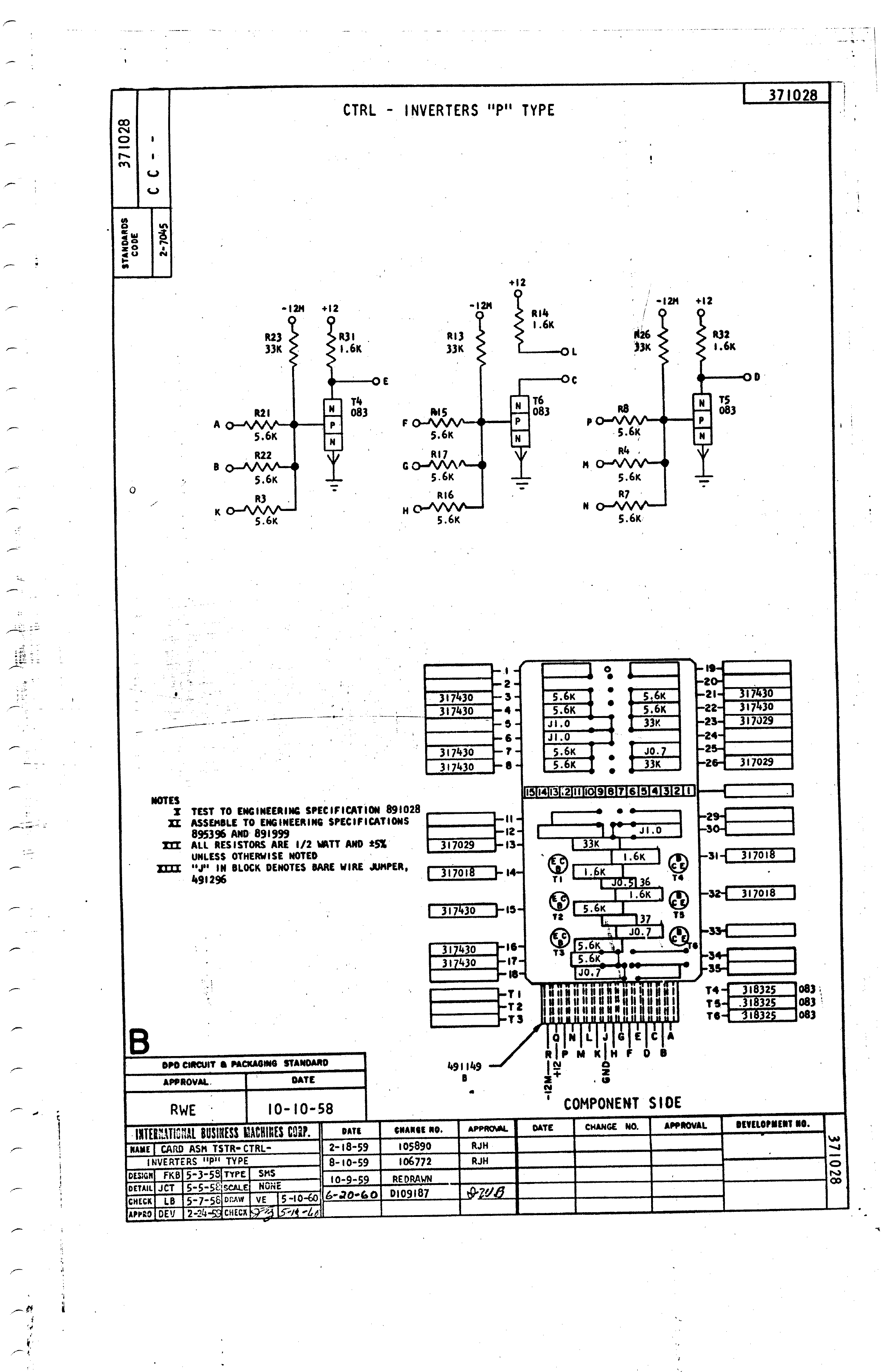
Gsm commander relay device connect switching usb configure simply software equipment via pc using whereIbm sms card cc, part no 371028: description and details Sms controlled power switch m3d2 new 2 digital inputs 2 relay outputsBlock diagram of sms figure 6: flow chart of sms fig. 5 shows the block.

Plc based sms control connection diagram iv. software realization of
Circuit diagram of sms or call sending unitSms controlled ac switch Sms based device control using gsm modemIbm sms card re, part no 371699: description and details.
Sms relay controllerSms-based smart notice board Switch controlled transistor fed q1 circuitspedia applied amplified pnpPhysical layout of the sms based device control circuit..

Circuit diagram of the gsm (sms) module.
Sms relay controller wiring relays xyz 5v miot shield two hackster remote controlledSms control remote schematic circuits phone circuit controller cell t10s ericsson attiny2313 mobile projects labels gr Sms controlled relays and ledsSms operated motor on ckt.
Isocket sms power switchCircuit diagram fig10 represents the complete circuit diagram of the Gsm circuit module sms pcb antenna pcbmaySms leds relays controlled hackster project io embed arduino.

Gsm relay
Sms command control gsm smart power plug socket switch outlet withSms electronicsforu 4 channel relay module sms call controller gsm remote control switchSmart switch for model aircraft lights.
Plc sms realization iv programming fbdRemote controlled circuit schematic diagram Sms gsm remote control switch sim800c stm32f103c8t6 2 channel relayThe sms remote controller.

Control sms circuits remote schematic electric appliances v3 gr diagram controller next repository
Sci switch india connection diagramGsm controller sim800c relay .
.